18 November 2021

14. Helix construction for west staging peninsula.

Having watched numerous youtube videos on helix construction, I decided to stick with the method I used on my last layout in Saint George, Utah. About the only change I made was in the material I chose to use. One of the videos I watched was by Joey Ricard from Trackside Scenery and he claims to have the world’s lightest helix. After watching his video, I totally agree. A 48” diameter, single track, 3 ring helix weighed less than 3.5 lbs. How did he do it? He used gator (foam) board. If you’re interested in seeing how he did it, you can watch this youtube video - World's Lightest Model Railroad Helix? - YouTube. Two disadvantages that I saw would keep me from using this method were the cost of gator board and the fact that the pieces were laser cut. The advantage if you don’t have the power tools or the patience and time to build it from scratch, you can buy the individual components in whatever size you want from Trackside Scenery. Since I didn’t want to shell out the money for the gator board (it's more expensive than plywood) or a custom helix, I opted to build my own using 3/16” plywood. The plywood cost was the same as 7/16” OSB and would be less than half the weight.

My first challenge was to figure out how to minimize waste of the plywood. Because of experience gained by building the helix for my previous layout, I knew I would use the basic isosceles trapezoid shape for sections of each circle, so the circle was divided into 16 equal sections. This meant that each pie shaped piece would have an interior angle of 22½°. Consequently, my cut on each end of a piece would be 11¼°. I decided I would need a track bed of 5” to give the needed clearance at risers for front end overhang on a Big Boy and inside curve overhang on long pieces of rolling stock. The helix track radius is 30 inches so I drew a circle with a radius of 32¼” and one with a radius of 27¾”.

When I purchased the plywood, I had the sheets ripped in half length wise to make it easier handling for me when ripping the individual lengths. With each piece 5” wide, I was able to get 8 pieces per sheet, 4 per half section. The long side of a trapezoid piece is 12¾”. I was able to get 8 trapezoid pieces out of each strip for a total count of 64 pieces per sheet of plywood. Now I know you mathematicians are saying, "Wait just a minute! If 8 times 12¾ is 102 and an 8' board is only 96", how were you able to get the 8 pieces out of one strip?" Easy - by making the first angle cut at the very end of a strip and then flipping the strip after each cut. And I didn't have to change the position of the saw blade for any of the cuts. Piece of cake! The remaining two narrow strips were cut into small 2x4” pieces that I then used to glue the joints of two trapezoids together. Bottom line – almost zero material waste, strong and light weight. Each completed semicircle weighs 2 pounds 1 oz.


My next task was to make the risers. I calculated that if I put 2 risers on each of the trapezoid sections, I would need 32 risers total - 16 on the inside and 16 on the outside of the helix - of which half of those would span 5 levels and the remaining half would span only 4 levels. I ripped some strips of the plywood 1½" and then stacked and clamped them together so I could cut the notches into one edge of the strips. I used my small router with a 3/16" bit to cut the notches. After all the notches were cut, I cut 16 lengths at 14½" and the remainder at 18½". These lengths gave me notches to accommodate 4 and 5 levels, respectively, with 1" extra at the top and bottom of each riser. Riser spacing was set at 4". 

After cutting all the risers, I was ready to start the assembly process. First was to start gluing the semicircles together. Once I had all of the pieces connected, it was time to start putting the risers in position. I accomplished this by putting the first 4 at locations 0°, 90°, 180°, and 270° just to hold it up while the rest were installed. I cut risers from pieces of the scrap 2" rigid foam insulation used to insulate the walls, making each one 1/8" higher the preceding one. Placing one riser in the center of every trapezoidal section - of which there are 16 in each circle - gives me a 4" rise between each level. After completing the first level, I used pieces of 2x4 cut to 3 7/8" as spacers to space each level and allow me to begin placing the risers onto the levels. After getting all the risers in place, I put a drop of super glue at each connection point to prevent the risers from moving. I didn't weigh the risers, but I calculate no more than 5 pounds total, added to 19 pounds for the 4.5 circles of plywood, the entire helix weighs less than 25 pounds. This makes for a very sturdy and robust helix. I figure at least one quarter of the weight of a helix made from 7/16" or 1/2" plywood with steel rods or wooden block spacers. So here you see the Alpha and the Omega. But what is it you don't see? Well, how about some cork roadbed and some flex track? Oooops!

Yes, I was so excited to put the helix together that I forgot to add the roadbed and track as I assembled the helix. BUMMER!


30 December 2020

13. The second peninsula is complete.

The first step in building the west staging peninsula is to layout the location with my laser level to establish the correct height in relationship to the east peninsula and the helix bases and make sure it is in the right location in relationship to spacing from the east peninsula. Then it's a simple matter of building several boxes that are 4 foot wide and join them together, working out to the end of the peninsula.

Since there is no pipe in the center of the end of the peninsula, I had to figure a way to make a post that I would be able to attach the radial arms to. I decided to use a 4x4 post, however, it would not be possible to attach the five arms to 3 sides of the post. A solution was needed so I put on my Tom Terrific hat and thought about it for a bit. I finally decided to fabricate a hub that would fit over the 4 sided post but yet give me 8 sides to attach the radial arms (only 5 would actually be used). As you can see by the photos, using pieces of 2x4, I built an octagon that would fit over the corners of the 4x4 post. I then used pieces of 1x4 to fill in the gap between the post and the inside of the octagon. Once this hub was completed, I was able to slip it over the post and slide it down so the top of the hub was even with the top of the framework. I anchored it in place with 4" lag screws. I then made a second one for the top level of the layout. You can see it resting in position on the top of a clamp secured to the post. Since the exact height of the main level is not known at this time, the post was cut a little longer than necessary and will be trimmed to the right length during construction of the main level.


After I had the hub in place and the radial arms attached, I then added additional supports for the purpose of supporting the fascia. I cut a piece of 1/2" rigid insulation with an outside radius of 36" to use as a template for the edge of the layout. After completing the framework, I installed the OSB, the asphalt board, and then painted both peninsulas brown, again using a $35 can of bad color mix from Lowes purchased for $9. Lastly, I added the fascia using hardboard strips cut to a 5" width. Next project - helix construction.


06 November 2020

12. Construction begins at last!

And so it begins . . . wood cut to length and screwed together. I know some of my local RR buddies were beginning to think I was all talk and no action since I've been talking about this for two years. But it has finally happened and I for one am thrilled to death. To date, I have constructed the base for helix one and two. Had to shift some plumbing leaving the well tank to get the clearance to allow the helix track to go between the pipe and the wall.


After getting the bases for helix 1 and 2 in place and level (at the same height), I started laying out the east peninsula for helix 2. I learned during the construction of the bases that the floor level varies as much as 3/4" from place to place. This prevented me from determining the height of one leg and then measuring and cutting 15 legs to one length. Thank God for laser levels! This will definitely be a cut-as-you-go project. Mass cutting of legs ain't gonna work! To determine the length of each leg, I placed my 4' rule in the spot where the leg will be and then read the measurement at the red laser line on the rule. Then I subtracted 3/4" from that measurement to allow for the adjustable foot at the bottom of the leg.

The framework was assembled using butt joints with pocket screws. My objective is to keep most all screws accessible after completion. This will allow for a support member to be relocated in the event it interferes with anything that protrudes below the base of the layout, for example, tortoise switch machines. Plus, the pocket screw joints are much stronger than simple butt joints.

Once the helix bases were framed up, I began construction of the first peninsula. The basic framework was built with 1x4 lumber. After attaching some extra support arms at the end to support a fascia, I installed the base sheet of plywood for strength and covered that with a layer of asphalt board for sound control. The asphalt board is similar to homasote but not as dense and only 1/3 the cost. Another advantage is that it can be cut with a razor knife so there isn't the dust mess to clean up after cutting like there is with homasote. A couple of coats of paint were applied so that track lines can be seen and to keep the asphalt coating from rubbing off on everything. The next project will be the peninsula that is connected to helix #1. Until then . . . keep your hand on the throttle and your eyes on the rail.


20 October 2020

11. Milestone 2 - Basement remodel complete

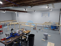
Yeah, again! The water leak repairs are complete and the front wall of the basement has been stabilized. I guess I wouldn't call this a remodel because nothing was done prior - just bare, cold concrete walls. So I installed 2" sheet insulation, dry wall, vinyl framed windows, window treatments, LED lighting overhead, vinyl cove base and plenty of electrical outlets. I painted the walls a very light gray and the floor a medium gray. So here's the before and after views . . .


As you can see in the bottom photos, I have lumber for the construction of the benchwork. The first phase of construction will be helix #1 in the alcove at the far left corner and helix #2 in the far right corner, around (actually above) the well tank. Zero elevation will be at 50" above the floor with the two staging areas at a -18" underneath, or 32" above the floor.

So, l'll get started today and keep you posted on my progress. Until then . . . keep your hand on the throttle and your eyes on the rail.

04 July 2020

10. Water, water everywhere!

Here it is Independence Day and not much is happening on the Ozark and Green Mountain. The embossed brick sheeting arrived but I didn't care for it. Hard to explain, just didn't appeal to me. I finally decided to go with printed photo paper using samples of red brick buildings I found around town and had photographed. I downloaded some photos of cinder block walls from the internet and printed them for the interior walls. This is what the two side walls of the roundhouse walls look like - interior view of one wall and exterior view of the other. Windows are currently just lying in place. Now I have to finish the 5 rear walls and 3 front walls.


As to the construction of the layout, that's been put on hold for some basement repair work. Remember that EASY fix to the water leak? It might have been an easy and cheap fix - if it had worked. It didn't! After having the situation examined by 3 different foundation repair companies this past week, major work to the tune of $10K is required and I have to remove the furring strips and insulation on part of one wall so the repairs can be made. Two options were proposed - repair from exterior with no guarantee or repair from the inside with a lifetime guarantee. Since this type of work is very common in this part of the state, it will be August before the work can be done. The front wall of the basement on the opposite side of the house is leaning inward 2.25 inches and has to be anchored in place and the leaks repaired. Sump pumps will be installed in both areas of the basement floor. Repairing from the interior doesn't prevent water from coming inside, it just diverts the water to a holding tank where it is then pumped to the outside of the house. I may be able to start on some benchwork on the wall furthest from where the leak is and work around to that point. Time will tell. Until next time . . . keep your hand on the throttle and your eyes on the rail.

16 May 2020

9. Still quarantined, but making progress

Well, here we are in mid May with some quarantine rules lifted but the economy is still tanked. Some restaurants are open for limited seating and hopefully more will follow. Among honey-dos and outdoor projects, I have made some progress on the roundhouse. The front and rear walls are complete. A dry run was done to see how all the walls fit together as a unit with the floor and roof support assemblies. 

Next was to add some locomotives in the stalls to get an idea of how much room I will have for interior details. I added two Big Boys and a Challenger since they are the largest I have.


I'm still waiting on the embossed brick sheets to arrive. They're suppose to be here by the 25th - that's 9 days. I won't make any more progress until I decide what type of brick finish I'm going to use. So until then . . . keep your hand on the throttle and your eyes on the rail.

02 May 2020

8. Quarantined progress

I was finally able to place the order for the basement windows. They should be done about the 10th of May and hopefully I'll get the installer to expedite the installation. I was told back in February they were 4 months behind for installation. In the meantime and after several rain storms, I was able to find the source of the water infiltrating the basement wall (a crack) and sealed it by spreading a coat of construction adhesive over the crack on the outside and after several more rain storms, wa-la! No more leaks. Thank God that was an easy and cheap fix!

Now as to the progress on the roundhouse, I am constructing the two roof support assemblies out of 1/4" basswood. My friend and fellow modeler (HOn3) John Scherr, did the drawings of all the walls and floor with his Cad program so the dimensional accuracy is no longer an issue. I was having great difficulty getting dimensions to come out correctly because, I think, of the inaccuracy of a small plastic protractor. Now I have perfect drawings to work from.

I first started construction by making the roof support assemblies. I distressed the basswood with a fine saw before coloring it with some black and burnt umber acrylic paint diluted with about 4 parts water. I then wiped off the paint to give it a lighter appearance. I placed a piece of wax paper over the drawing template so that any excess glue would not stick to the drawing.  Before installing them on the floor of the roundhouse, I will probably dry brush them with some gray paint to give them a more aged look. Both assemblies turned out identical in size thanks to the excellent drawings I had to work with.


After completing the roof support assemblies, I then tackled the 2 side walls. Again, using John's drawings, I laid out the template on a 12 x 24 inch sheet of .080 styrene. After transferring the outline for both sides to the styrene, I began the process of cutting them out. The windows were a killer to say the least. After drilling out the center portions, I cut away most of the remaining material with an exacto knife. I then fine tuned the edges with a nibbler. First time using it and it's a great tool. I then did a little filing to make a perfect fit for the windows. Next time, I will not drill out the centers, but instead drill 4 small holes near the inside corners of the window openings and then use a dremel and cut-off disc to remove the center mass. Then I will use the nibbler. Live and learn.


The final step was to install some .080 x 5/16" strip styrene around the edges. I'm not sure, but I think the 4 vertical pieces will represent concrete columns as opposed to brick. The majority of the structure will be brick but I am as yet undecided as to how it will be represented. My options include homemade decals using photos I took of a brick wall on a building at Lincoln University in Jefferson City, photo paper with printed brick, or embossed paper bumpy textured stone brick wall (at least that's what I ordered). Obviously there will be more to come on this topic.


Next up will be the construction of the front and rear walls, so stay tuned.

24 March 2020

7. Coronavirus Down Time

 Well, as all of you know by now, most of us have been semi-quarantined to our homes because of the virus. As a result, my insulation installation project has ground to a halt until I can get the replacement windows ordered and installed. So in the interim, I have been working on some structures that will be going on the layout. The first one, a Faller kit, is a cement mixing plant. Here are a couple of photos of the construction and final weathered plant. The photo on the right does not show the weathering as clear as shown in the center photo. I used a white wash on this structure since it will be sitting amongst the gravel, sand and cement, which I figure will create a lot of white dust. I haven't named this industry as yet. Like the previous layout in Utah, names of industries, buildings, rivers, etc., will be named after family members. I want to try my hand at making my own decals before I put any signs up. Now that I think about it, I should have waited till the sign was put on the silo to do the weathering. The next structure will be the roundhouse, which I am building from scratch. See you on the next post.


14 March 2020

6. Insulation installation

To date I have installed insulation on 2 of the 3 primary walls (west and north). These photos show the 2 inch foam insulation held in place by horizontal 1x4 boards and then vertical 1x4 furring boards on top.  Some will ask why I didn't just use the vertical boards to hold the foam insulation in place and forgo the horizontal boards. By using two layers of 1x4 boards, I create a 3/4" chase both vertically and horizontally to run my electrical conduit and the main water line from the well tank to the other end of the basement where the water heater and softener are located . Also, my electrical boxes can be installed flush with the interior drywall surface and only require me to remove little to no foam behind the boxes (depending on the size box used) instead of digging out almost all of the foam to allow the box to be recessed sufficiently to be flush with the interior drywall surface.


I installed half of the insulation on the east wall Friday. It rained Friday night and Saturday morning and when I went to install the rest of the insulation - you know where this is going, right - I found 2 puddles of water on the floor, one on the north wall that had the insulation glued and nailed in place and one on the east wall in an area to be finished today. Here are photos showing the 2 areas. The water has collected inside the area I marked with a Sharpie and is a little hard to see, but it's there. The leak on the unfinished wall is readily identifiable as a crack on the outside of the wall that can be easily sealed. Unfortunately, the leak on the north wall that is already insulated will require me to dig out away from the foundation to find the location of the leak and seal it. Not looking forward to that task!


Also, while working on the north wall around the two windows, I decided the 40/50 year old single pane, aluminum framed windows should probably be replaced at this stage. I removed the security bars that were on them and have framed around them and now waiting for replacement windows to be installed.


With the main line track elevation at about 50", it will be about half way up the larger window. Then with a 20-24 inch backdrop height, the window will be about 90% covered while the railroad is up. Whenever it is removed, there will not have to be any repairs made to the walls or windows since the bench work will be free standing but built against the walls.